THE TOUR ENGINE IS A PATENTED, SPLIT-CYCLE, INTERNAL COMBUSTION ENGINE THAT STANDS TO DELIVER SUBSTANTIAL EFFICIENCY GAINS THROUGH SUPERIOR THERMAL MANAGEMENT
Unlike current combustion engines, which use the same cylinder for all four strokes (intake, compression, combustion, and exhaust), Tour’s patented engine design splits the conventional 4-stroke cycle between two cylinders: the cold-cylinder hosts intake and compression, and the hot-cylinder hosts combustion and exhaust.
A PROPRIETARY CROSSOVER VALVE IS USED TO TRANSFER THE COMPRESSED
CHARGE FROM THE COLD-CYLINDER TO THE HOT-CYLINDER.
This thermal management strategy reduces the magnitude of the two major efficiency losses in
conventional 4-stroke engines – heat loss to the coolant/oil and exhaust energy loss.
The end result is a thermally optimized engine that advanced computer simulations and working prototypes suggest can be as much as 30% more efficient; dramatically reducing both fuel costs and noxious emissions. Better still, because Tour Engines employ the same “block and piston” architecture that has been at the heart of ICEs for more than a century, they will be inexpensive to manufacture, adopt and maintain.
")
Learn more about Tour Enable
SUPERIOR THERMAL MANAGEMENT
The Tour split-cycle engine implements a superior thermal management strategy that reduces the magnitude of the two major thermal losses in conventional 4-stroke engines – heat loss to coolant/oil and exhaust energy or enthalpy loss.
The Tour cycle separates the cold and hot portions of the full thermodynamic cycle to separate cylinders, enabling less heat loss to both the induction/compression and combustion/exhaust strokes
PROPRIETARY TRANSFER VALVE
Measured pressure traces from the 1 kW Tour engine developed with support of the ARPA-E GENSETS program.
![]()
The measured pressure traces illustrate the fluid transfer between cold- and hot-cylinder and follows the complete Tour cycle: The reciprocating shuttle alternately connects through the ‘Input Port’ (IP) during phase with the cold-cylinder and through the ‘Expansion Port’ (EP) with the hot-cylinder during phase . Ignition during phase initiates combustion at a crank angle of -6° (red arrow). During phase , almost the entire trapped mass in the cold-cylinder is compressed into the shuttle volume (blue arrow) where it combusts during phase and expands into the hot-cylinder during phase . The induction and exhaust through conventional poppet valves occur during phases and , respectively. Note that there is no pressure drop during the fluid transfer through both ports as the shuttle pressure coincides with both cold- and hot-cylinder pressures during phases 1, 3.
CLEANSHEET ENGINE DESIGN
A clean sheet engine has been designed, built and is currently being tested
Based on detailed system simulations (GT-Power), first performed by Tour Engine, Inc. and independently confirmed by Wisconsin Engine Research Consultants (WERC, which are a subrecipient of this project), the engine in this project has been designed with an expansion ratio of nearly two times the compression ratio and each cylinder has been fitted with a dedicated cooling circuit to characterize and subsequently minimize the heat losses of the engine. The combination of these two features provides the theoretical basis for significant efficiency gains of the Tour split-cycle over conventional engines.
DEVELOPED IN SAN DIEGO
Tour Engine built a state-of-the-art engine development and test facility in San Diego.
INCREASED THERMAL EFFICIANCY
Increase thermal efficiency based on first principle on 1D computer simulations
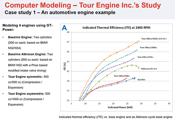
The efficiency of the split-cycle approach is significantly improved by over-expanding the gas in the Hot-Cylinder (as in the Atkinson cycle for naturally aspirated engines and the Miller cycle for forced induction engines), which has the two-fold benefit of increasing the mechanical work extracted and lowering the average gas temperature at the Hot-Cylinder (Over expansion has an advantage also of lowering the temperature differential driving the heat rejection to the Hot-Cylinder. See “Superior thermal management strategy” above).
The Figure below (Panel A) depicts indicated thermal efficiency (ITE) results at a fixed speed of 2400 rpm from GT-Power simulations for three engine configurations: a 2-cylinder baseline 4-stroke engine with 1000 cc (blue, solid line), an Atkinson cycle engine (green, solid line) and various Tour cycle engines (dashed lines). A symmetric Tour engine (red, dashed line) with 1000 cc (500 cc compression/500 cc expansion) has only a slight advantage over the baseline but asymmetric (over-expanded) Tour engines gain a significant advantage up to 1500 cc (500 cc compression/1000 cc expansion).
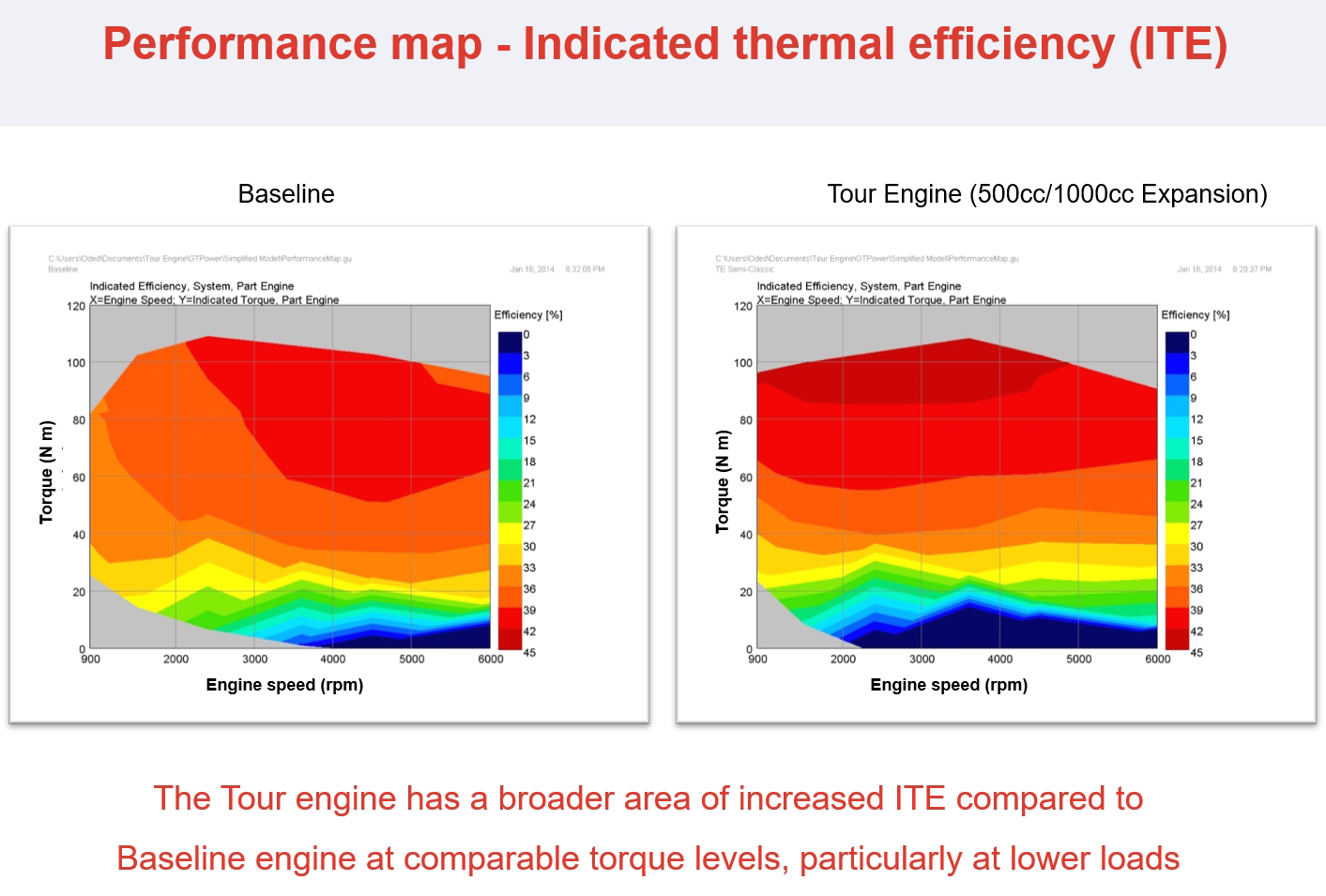
Combustion strategies similar to those used in the Atkinson cycle enabling a 13:1 compression ratio would further increase the efficiency of the Tour cycle (orange, dashed line). The results at 2400 rpm suggest that overexpansion of engines with the above stated displacements can increase indicated thermal efficiency (ITE) relative to the baseline by up to 19%, and relative to the Atkinson cycle by up to 13% depending on the specific engine configuration. In order to simulate the performance maps (shown with ITE contours) for the baseline engine (Panel B) and the over-expanded Tour engine (Panel C), a throttle was added to the models. The performance maps show a higher ITE for the Tour engine and an expanded high efficiency region across a wide range of engine speed, including low engine speeds. This is advantageous for increasing engine durability while maintaining high efficiency.
POWER STROKES
The power stroke in the Hot-Cylinder and the intake stroke (of the next cycle) in the Cold-Cylinder occur concurrently.
Hence in a pair of Tour engine cylinders, two 4-stroke cycles are being executed at the same time. In this respect, the Tour engine and a conventional four-stroke twin engine have exactly the same number of power strokes per crankshaft revolution. For example, a conventional twin engine will have one power stroke in each cylinder, while the Tour engine will have two power strokes in the Hot-Cylinder and none in the Cold-Cylinder.
EARLY DEVELOPMENT
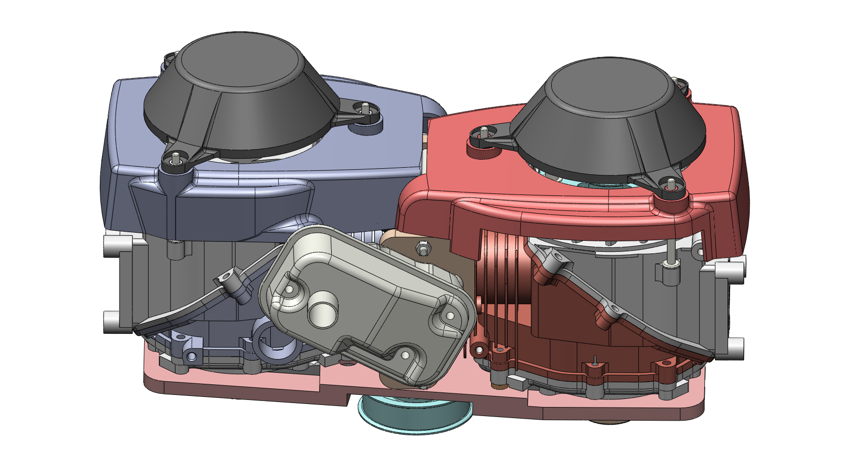
As demonstrated from early prototypes and modeling, TEI has built at its R&D facility in Israel two functional prototype engines that implement the Tour cycle.
The first prototype, Prototype I, became operational on 2008 and used two identical off-the-shelf 50cc Honda GXV50 engines, one for the Cold-Cylinder and the other for the Hot-Cylinder. Prototype I proved the mechanical feasibility of the Tour engine design and showed for the first time that the crossover valve can be built in such a way that there is very little energy loss due to the transfer of the working fluid from the compression cylinder to the expansion cylinder.
Tour Engine Prototype I
- Design. Two Honda GXV50 engines were connected with the crossover valve positioned at the interface between the two cylinder heads.
- Assembled. Notice that over 85% of the prototype parts are taken from off-the-shelf engines.
The second prototype, Prototype II, became operational on 2012 and is based on two identical off-the-shelf 190cc Briggs and Stratton engines.
Prototype II was designed primarily as a platform to test, in a modular fashion, various crossover valve designs. This prototype was later modified to implement an over-expanding of the gas in the Hot-Cylinder (as in the Atkinson cycle), and a movie of this prototype being tested in our R&D facility in Israel can be seen here.
REIMAGINE THE FUTURE WITH TOUR ENGINE
Tour is backed by sophisticated technology investors and has won grants from both the US (DOE’s ARPA-E) and Israeli (DOE) governments. Tour has also been issued 45 patents (US and International) with several more pending.
LEARN ABOUT MORE WAYS YOU CAN GET INVOLVED WITH OUR TEAM